Your benefits at a glance:
- A digital data model as single source of truth of engineering data for automated analyses and source for information systems
- Process parallelization gives shortened development times
- Experts from the mechanical and electrical world work in their familiar environment, optimized for their tasks
- Communication security and project overview
- No multiple entries, no manual additions, significantly fewer errors
- Changes can be implemented much faster and more consistently
- Possibility of automatic analysis of cross-discipline data on the digital model
Challenges
- Process reliability: Consistent data exchange between electrics and mechanics
- Process acceleration: Electrics and mechanics are each dependent on data from the other discipline - and have to exchange information, which means waiting for information
- Quality improvement: Manual entry of the same data in different systems is time-consuming and error-prone
- Comprehensive analyses: Automatic evaluations of cross-discipline data are not possible without a digital model.
Worlds come together in the development of harnesses for mobile systems. In vehicle design, the mechanical experts try to accommodate components in the smallest possible space and to optimize the mechanical design of the system. That alone is a great challenge. In addition, there are more and more complex electric vehicle components. The vehicle topology specified by the mechanics has an influence on the electrical design. Designing and accommodating all the required functions is correspondingly demanding and time-consuming for electrical development.
The earlier electricians have mechanical information available, the earlier these properties can be incorporated into the development. And the earlier mechanics have information on the installation space requirements of the electrical system, the earlier this can be taken into account in the mechanical design.
A sensible parallel development of mechanics and electrics means that data must be continuously synchronized. However, in today's data overload, manual data transfers are far too time-consuming and error-prone, and an overview of where to find what information and which version of one discipline belongs to which other data version is almost impossible. But how do you get the right calculation? How can we efficiently check whether the entire system works? This requires analysis options – and the data must be able to be exchanged and synchronized equally quickly and reliably without manual input.
Solution
Synchronous at all times
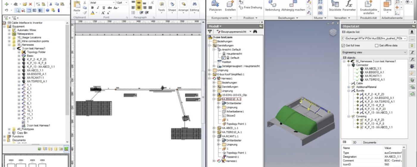
AUCOTEC offers a particularly integrated solution for the harness design process: the Platform Engineering Base (EB) with its object-oriented data model, which allows the definition of different views of the centrally stored data. Whether electrologic, 2D topology or 3D model, EB provides an overview of all the planning data at all times and enables a highly efficient change process.
In cooperation with the 3D experts of leading tools such as CATIA, NX, Creo or Inventor, AUCOTEC develops standardized couplings to EB Cable, the harness design version of Engineering Base. They significantly facilitate the interaction of mechanics and electrics, because they allow both sides to start the design process in parallel and to synchronize the respective information at any time. With automated, bi-directional data exchange between the systems, the planning process as well as the change process is considerably accelerated, and with the significantly improved data consistency, the quality of documentation is also improved.
Automatic derivation
EB is the definitive system for the electrological definitions – i.e. the determination of the electrical components and connectors. The resulting harness data developed in 3D (topology, length, protection material) is returned to EB Cable. The routing of the individual wires takes place there and the 2D harness derivations and subsequent documentation, such as formboard drawings, lists, etc., are generated automatically. All changes can be traced exactly and transferred from one system to another.
Advantages
Faster, more consistent, cheaper
This integration solution for 2D and 3D engineering allows exceptionally consistent harness development for any type of on-board system planning - without data breaks due to system transitions, double data entry or manual additions. This eliminates sources of error and improves quality while at the same time saving a great deal of time.
In addition, the overview of the current status of a harness design process is made considerably easier. And thanks to the automated exchange of information, changes are recognized immediately and cannot be overlooked or forgotten.


